Instruction Box of M7MI Super hydraform brick block machine
Forward
The manual introducing for the user of the Shandong Geothy Machinery Company Limited production of the instruction box of M7MI Super.It detailed introduce the features,structure,function,installation,maintainance,operation and fault handling etc. M7MI manual is the one which must be read by the management,operation and maintenance workers.
Also it will help you quickly for you to get to know and mast our machine,in case of damage of unfamiliar and then achieve the sales goal.
Attention:
When using this machine, please strictly in accordance with the provisions of this manual for use;
A failure occurs, please contact with our company, in order to quickly avoid affect your normal use;
The machine will be constantly updated design, modify the content will not be informed;
In the future, about the contents of this manual, could not explain such changes;
Catalogue
1.Usage and characteristics ┈┈┈┈┈┈┈┈┈┈┈┈┈1
2.Main technical parameters┈┈┈┈┈┈┈┈┈┈┈┈┈1
3.Parts and introduction┈┈┈┈┈┈┈┈┈┈┈┈┈┈┈┈┈┈2
4.Checking and debugging┈┈┈┈┈┈┈┈┈┈┈┈┈┈┈┈┈3
5.Operation and guidance┈┈┈┈┈┈┈┈┈┈┈┈┈┈┈┈┈┈4
6.Material choosing┈┈┈┈┈┈┈┈┈┈┈┈┈┈┈┈┈┈┈┈8
7.Raw material ratio┈┈┈┈┈┈┈┈┈┈┈┈┈┈┈┈┈┈┈10
8.Screening and mixing┈┈┈┈┈┈┈┈┈┈┈┈┈┈┈┈┈┈11
9.Maintenance ┈┈┈┈┈┈┈┈┈┈┈┈┈┈┈┈┈┈┈┈┈13
10. Equipment failure and elimination method┈┈┈┈┈┈┈┈┈14
11.Products’ curing ┈┈┈┈┈┈┈┈┈┈┈┈┈┈┈┈┈┈┈14
12.Safety procedures and precautions┈┈┈┈┈┈┈┈┈┈15
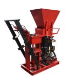
一、 Usage and characteristics
Our company produce the Hydraform interlocking brick machine, is the special equipment which
can make the construction interlocking bricks.By changing different moulds and using
cement,sands,clay,fly-ash and white lime etc to make different types and sizes
interlocking blocks.Prime mover is hydraulic system.hydraulic components are imported original
parts or domestic equipment of national famous brands,with exquisite structure, reliable
performance,easy operation,low malfunction,strong applicability and simple maintenance as
characteristic.Hydraulic cooling system is controlled by a temperature controlling switch, run
automatically according to the hydraulic oil temperature, reducing energy consumption. Finished
products molding from hydraulic system driver, hydraulic pressure to make it complete. The
production of interlocking bricks bearing strength can reach above 16-20Mpa (Zhao Pa), high
compactness, frost resistance, impermeability performance is good, sound insulation, heat
insulation, and also heat preservation performance is good, appearance size accurate, is the ideal
environmental protection and building materials equipment.
二、 Main technical parameters Instruction Box of M7MI Super
1、Machine size 2900x1500x1600 mm
2、Rated hydraulic pressure 16-20Mpa
3、Forming way Static pressure
4、 Brick size
Length:230-290mm Width:200-220mmHight100-115mm
5、Molding cycle 10 s
6、Total power 18Hp
7、Totale weight 1000 Kg
Checking and debugging
4.1、Checking –
The machine is tested ex-factory in motors,electric and oil parts unite
test.Each component has been adjusted according to the design, the
position is relatively correct. Motion and position accurately, the
performance of the machine is reliable,the machine is released by
successful inspection. Due to the probably rough transportation,please
check the machine if there is any damage,parts missing and any position
changes.
4.2、Debugging
(1)Check all the parts,add hydraulic oil into the oil tank which is
suitable by 2/3 level of it.
(
2)Add diesel oil into the machine and start.(3 )Power on the pump motor,checking the turning direction,if
opposite there will be no pressure.
(
4)Check the system pressure:The pressure is set up ex-factory,so
there is no need to change or adjust it any more during normal operation.
(5)Power on the oil pump,operate the handle(no action for the
brick machine) and check if the oil pump is work well.Check all the
circuit connection,and also the mechanical parts function,to see if there is
any abnormal of the machine.
五、Operation and guidance
5.1、Machine’s operation
Remark:Only one person needed to operate the machine for
production.
Control value’s operation:
The brick machine is of two hydraulic cylinder,each of them is worked
dependently.Any of them while working,the other one is in the free
position.
Face the machine,in front,seeing two control handle in both sides of the
machine.
Left side:control the lower mould up and down cylinder,push the handle
upward,lower mould cylinder is out and move upward.Press thehandle,the lower mould cylinder move backward,lower mould move
downward.
Right side : control the upper mould up and down cylinder,push the
handle,upper mould cylinder come out,upper mould move upward;push
the handle,upper mould cylinder move backward,upper mould upward.
There is ball-non-return value in the back of shaping frame,once start,the
mixer is under working and once power off,the mixer will be stop also.
5.2、The pressure adjustable
The setting pressure is 90-100BRA(9-10)MPa,there is no need for usually
adjustable the pressure.
If the sands contents is higher,then can change the pressure into
120-200BRA(12-20)MPa.
If there is too much clay,then can change the system pressure
into60-80BRA(6-8)MPa
5.3、Pressure changing operation
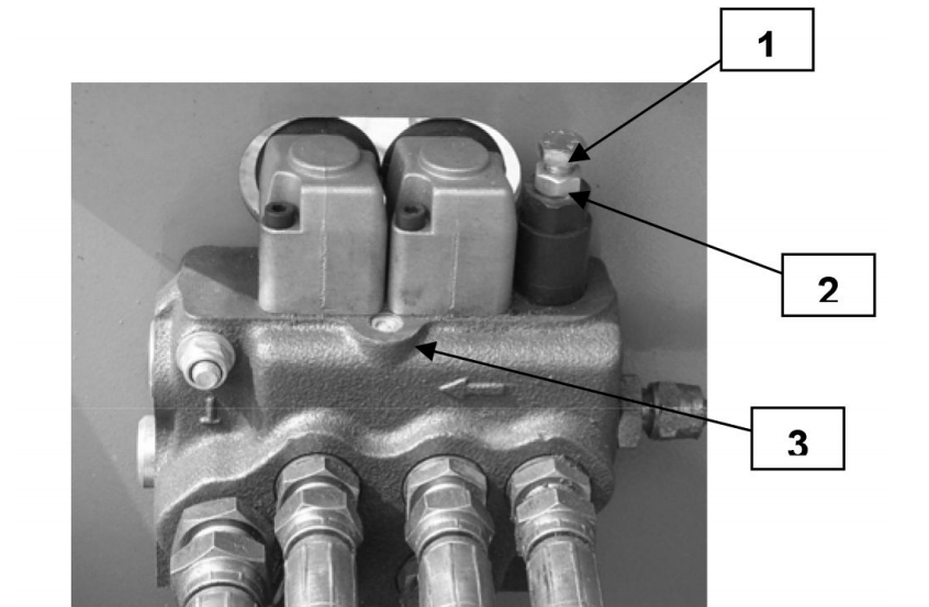
1、Open the locknut(2)
2、Take out locknut(1),low the system pressure
3、Tight(1),raise the system pressure
Remark:Make sure that the upper mould head is in lift position while adjusting the system
pressure.
5.4、Operation procedure
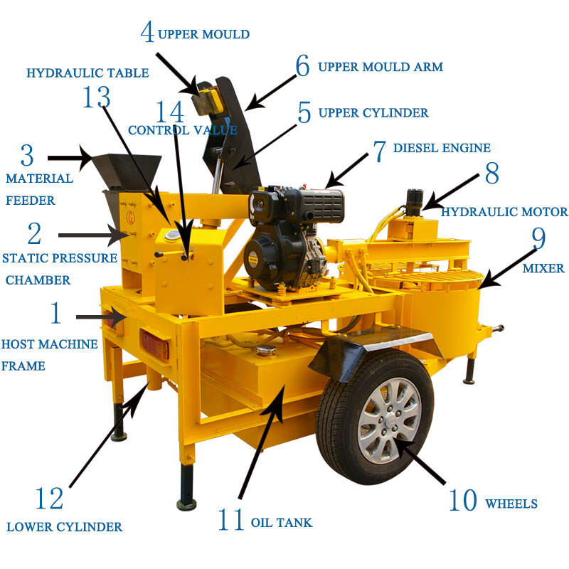
Reference picture 1
1.Power on the diesel engine(7),open the control value of the mixer,start the mixer(9)
2.Put clay and cement into the mixer(9)
3.Adding water into the mixer evenly into mixer(9)and mix the raw material.
4.After mixing,open the discharge mouth and download the ready material.
5.Move the cylinder connected with the lower mould(12)into backward,let the lower mould in the
lowest position.
6.Move the cylinder(5)connected with the upper mould(4)in the out position,let the upper mould(4)in the highest position.
7.Material feeder(3),after it is full of material.
8. Put the material feeder(3)into the above side of mould(2),after the material is full of the
chamber,move the feeder back of the original position.
9.The cylinder connected upper mould(4),set it backward,press the upper mould head into the
shaping chamber until arm(6)connected with chamber(2)upper mouth.
10.Extend the cylinder(5)by controlling upper mould(4),move arm(6)away,then upper mould
(4)is in highest position.
11.Extend lowered mould connected cylinder(12),push the finished products into the highest
position.
12.Move back the cylinder connected the lower mould(12),let the lower mould back the original
position.
13.Take out the finished bricks.
After finished one circle,repeat the procedure from 5—13.
5.5、Moulds changing
5.5.1、The reason for mould changing – Instruction Box of M7MI Super
1、In the pressure chamber(2),there are four pcs durable mould shaped the mould,but after
long time run using and brushing,and after times of these the mould should be a little worn.When
the finished products sizes are much different,then the mould should be changed and keep the
brick size evenly in the fault range.
2、When you need producing different size of bricks,then there also need to change different
mould.And every mould has a full set of moulds pcs.
5.5.2、The process of mould changing
1.Upward the arm(6),take out upper mould(4).
2.Control lower mould’s connected cylinder(12),let the lower mould being pushed out of the
chamber,take out the lower mould.
3.Control the lower mould’s connected cylinder(12),let the lower mould move back to the
original position.
4.Power of the diesel engine(7).
5.Rake out the chamber(2),four sides 24 screw nuts out.
6.Take out the four pcs chamber moulds out.
7.Clean up the chamber.
8.Put the ready changed moulds into the chamber(2),put the four sides screw nuts.The upper
surface of the mould should be in the same level of the chamber upper surface.
9.Power on the diesel engine(6),control the lower mould cylinder(12)extension,let the piston
rod out and connect the lower mould into the rod.
10.Control the lower mould cylinder(12)backward,let the lower mould downward into the
chamber,adjust the chamber(2)’s screw nuts which around to suitable position until the moulds
can move freely in the chamber up and down.
11.Connect the newly changed mould(4)with arm(6),control the upper mould cylinder(5),
put the mould pressed into the chamber,adjust the chamber(2)’s screw nuts until the upper
mould(4)can freely move into the chamber.
12.Control the upper mould cylinder(5)and lower mould connected cylinder(12),adjust the screw
nuts,make sure the upper and lower mould can move freely in the chamber.